
BRIDGE ASSEMBLIES
(TYPICAL)
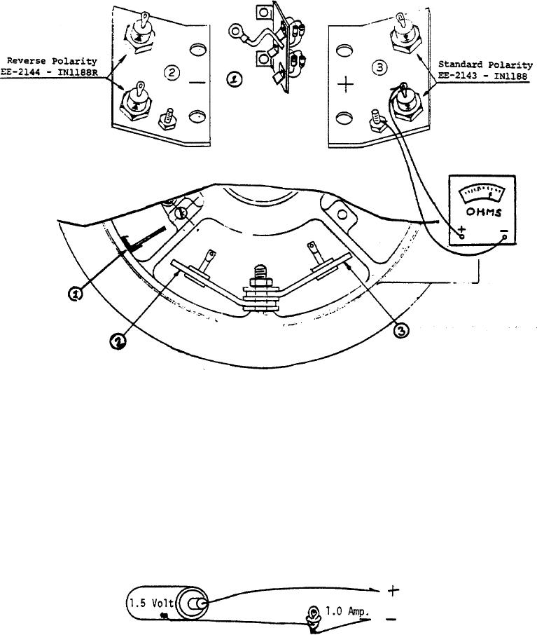
1. Base Field Rectifier Bridge Assembly
2. Negative Control Field Rectifier Bridge Assembly
3. Positive Control Field Rectifier Bridge Assembly
Caution: When replacing diodes a solider connection is required. It is very important that the solder joint is made
quickly. Use a hot iron and remove immediately when the solder flows. The diode can be destroyed by prolonged heat.
Check the diode with the ohmmeter before installing.
Check for Defective Diode
1.
Disconnect all external wiring from both AC and DC circuit. (Carefully mark the point of connection of each wire to
assure proper re-connection).
2.
A diode that is in good order will conduct current in one direction and block in the opposite. The conducting
direction is marked on the case by an arrow and by a color band on the smaller
3.
Use an ohmmeter (or a 1.5 volt flash light battery and bulb as illustrated) to check the current direction. Connect
positive at the base of the arrow and negative at the end to which the arrow points. (See illustration) A diode that
conducts in both directions or neither direction is defective.
Alternate means for testing a diode if an ohmmeter is not available.