
STATOR ASSEMBLY
Note:
When ordering replacement stator assemblies be sure to include the model and serial number from the
nameplate on the side of the generator.
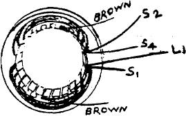
The stator assembly has a winding to develop voltage for the base field. The lead extensions from this winding are
colored brown. Connection from this winding is to the base bridge.
A single, two pole winding is used for two wire, single voltage models. This winding connects to the control (Series) field
bridge. The control bridge is divided into a positive and a negative side and is in series with the load. (See bridge
assembly illustration)
Three wire, dual voltage models use two identical, two pole windings. Each winding generates 125 volts. The voltage
from either line to neutral is, therefore, 125. From L1 to L: the winding is in series for 250 volt output.
When a fault in the stator is suspected each individual winding should be checked. The resistance of 'the separate
windings will be low, less than one ohm, but a complete circuit should be indicated. IE: #S1 to #S2, #S4 to #L1.
The various windings should also be checked for ground. For this purpose connect an ohmmeter from a bare spot on the
frame to one lead of each coil. A meter deflection indicates a grounded winding.
When all stator leads are disconnected, there should be no circuit from one winding to any other. If a circuit is indicated,
the winding is shorted.
If any of the above conditions are indicated, the stator assembly must be replaced.