
Figure 19 - Tilting Hopper Wings
Figure 20 - Screed Lift Cylinder - Cut-away View
(19) Screed Lift Cables - Raising and lowering of the heavy screed assembly is accomplished through an
arrangement of hydraulic cylinders, flexible cables, and pulleys. (See Figure 20). Because of the mechanical portion of
the system which is for the most part hidden from the operator's view, it is wise to examine the cylinder operated pulley
through the under side opening in any event of uneven screed movement. This will eliminate unnecessary hydraulic
system trouble-shooting in the event the actual cause is the binding or jamming of a cable.
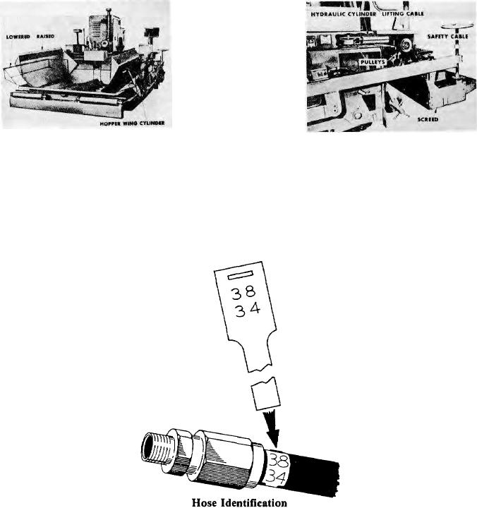
(20) Hose and Tube Identification - Each hose and tube is identified with a tag on one end as shown in Figure
21. The number shown 38-34 corresponds with the last four numbers of the hose or tube assembly part number 5032-
201-38-34.
Figure 21
(21) Hose Assembly - The rubber-covered wire braid hoses used throughout the hydraulic system will give
trouble-free service and long life if properly maintained.
Periodically check hose position to make sure they are not rubbing against moving parts or supported on sharp
steel edges.
The hose end fittings are (no skive) re-usable hose fittings, to make it possible to repair the hose on the job site.
Replace rubber-covered hose as follows:
(1) Disassemble fitting nipple by turning it out of hose socket.
(2) Disassemble hose socket by turning it off the rubber hose.
(3) Clean steel socket and nipple.
(4) Dip ends of new hose into hoze-oil lubricant and then thread the socket onto the rubber hose.
Do not cut inner or outer covering for assembly.
(5) Thread nipple to socket.
(6) Clean fitting and interior of hose. CAUTION: Flush hose with solvent before installing into system.
Page 43