
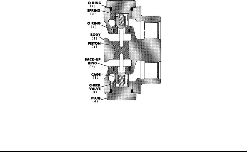
(15) Holding Valve - (See Figure 14)
The holding valve is a double acting check valve assembly with a floating piston for power unseating of the two spring
loaded check valves. When pressure is applied to one of the actuating ports the spring loaded check valve on the
pressure side of the housing is unseated and fluid passes to the hydraulic cylinder. The piston is moved by the same
pressure to mechanically lift the opposite check valve off its seat, permitting the return flow from the cylinder to pass
through the valve to the reservoir. When there is no pressure applied to either actuating port, both check valves are
seated and no flow to or from the cylinder can occur. The cylinder piston is therefore locked in position and the unit it is
powering is "held."
The holding valve can be dismantled and checked internally or repaired as follows:
A - Unscrew and remove Plugs (4).
B - Remove Springs (2) and Check Valves (9).
IMPORTANT! Each Check Valve (9) must be reassembled in its match fit Cage (8).
Keep these parts separated from the duplicate set on the opposite side of the valve so
that no accidental interchange can occur.
C - Using a short length of rod small enough in diameter to pass through the bore of one of the Cages (8) carefully
drive the Floating Piston (5) against the opposite Cage to force it out of the housing. The piston will follow the cage out
of the housing.
D - Carefully re-install the piston in its bore, with the opposite cage downward. Use the rod again to drive the
piston against the cage until it is also clear of the body.
Inspect the piston and the bore of the housing for scratches, score marks, or particles which may have caused a
binding or jamming of the piston. Test the piston in the bore for completely free movement, turning it through several
revolutions slowly as it is drawn back and forth. There should be no indication of binding.
Inspect check valves and cages at the contact area for nicks, scratches, and fluid erosion grooves which can permit fluid
passage. Do NOT attempt to re-machine these parts. Obtain replacements.
IMPORTANT! When replacing cages be sure to use reliable O Rings (3) and Back Up
Rings (7) and arrange them in the proper order as shown in Figure (14).
IMPORTANT! When re-attaching the assembled valve to the valve bank, tighten
mounting screw evenly and use not more than 150 inch pounds of tightening force.
Uneven or excessive tightening can distort the housing and bind the piston in its bore
making the valve erratic or inoperative.
(16) Pressure Relief Valve (See Figure 15)
The system pressure relief valve is a spring loaded ball type assembly which is externally adjustable. A new valve
is adjusted by the manufacturer to limit system pressure to approximately 1200 PSI.
Dis-assembly: The valve can be dismantled for inspection, cleaning and part replacement. (Refer to Figure 15)
(1) Unscrew and remove CAP (A).
(2) Loosen and remove LOCKNUT (B).
(3) Unscrew and remove ADJUSTING SCREW (C).
(4) Unscrew and remove HOUSING (E) from BODY (F).
(5) Push out SPRING (D), GUIDE (G) and BALL (H).
Page 40