in the wiring from the operator's console to the junction box or from the junction box to the solenoid valve. If a visual
check of the junction box does not disclose any broken wire, consult a qualified electrician. (Use paver electrical manual)
(b) If no sparking occurs at the console case, the problem is more complex and a qualified electrician should be
consulted.
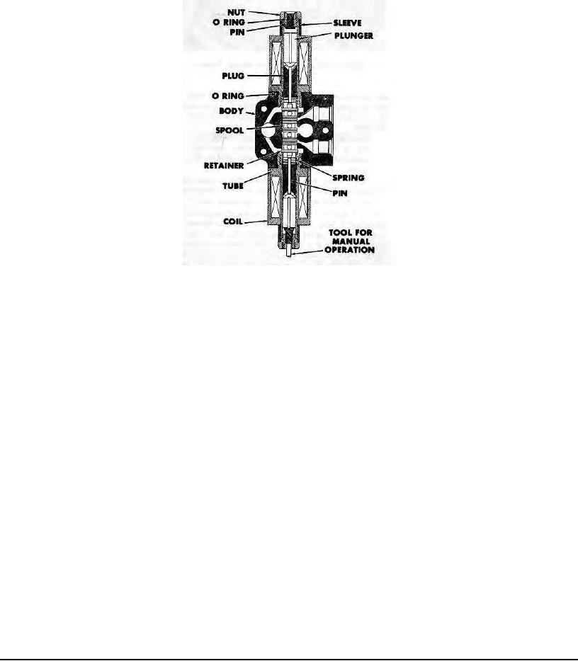
Figure 9 - Solenoid Valve - Cross Section
(9) Solenoid Valves - All of the 4-way solenoid operated directional valves used on the paver are identical units
(See Figures 9 and 10). They are double acting valves with spring return of the spool to the neutral position. The
operation of each valve is controlled by a double throw toggle switch on the operator's console. When one of the switch
contacts is closed, a 12 V.D.C. valve coil is energized and the spool position is shifted by the plunger to connect internal
porting so that hydraulic fluid under pressure flows to one end of the hydraulic cylinder(s). Fluid displaced by the moving
cylinder piston flows through aligned ports of the same solenoid valve to the reservoir. When the toggle switch is moved
to the opposite position, the opposite coil is energized and the spool is shifted to reverse the pressure and return flow
ports so that the cylinder moves in an opposite direction. When the switch is at the central "OFF" position the spool is
centered in the valve body by coil spring action and all ports connected to cylinders are closed so that no flow to or from
the cylinders can occur.
(10) Solenoid Coil Testing by Substitution - If a coil is suspected to be the cause of a hydraulic system's
failure, exchange the questionable coil with an adjacent coil which is known to be functioning properly.
METHOD: (See Figure 10)
A - Remove Nut (1) and Sleeve (2) from each coil.
B - Grasp Coil (3) and twist gently back and forth while pulling unit away from valve body.
C - When both coils are clear of their tubes (6) slip the good coil onto the tube of the inoperative system and the
questionable coil onto the tube of the functioning system. Install the sleeves and nuts.
D - Do not change the wiring connections. Operate the toggle switches with the exchange of coils in mind.
Example: If the screed lift was inoperative and the hopper wing coil is substituted, operate the Hopper Wing
toggle switch to test the screed lift system (and vice versa). If the substitute coil will not operate the screed lift system,
but the coil removed from it will operate the hopper wing system, then the screed lift valve may be jammed internally so
that it cannot be operated electrically. Put coils back in original locations and make a manual actuation test as outlined
in Paragraph (11).
If the substitute coil operates the troublesome system properly, interchange only the hot wire of each coil (quick
disconnect type). See if the substitute coil will still operate the valve when connected to the troublesome system's wiring
circuit. If the system again works properly, the suspected coil is truly defective and should be replaced. If the system
fails to work with the original wiring or if the suspected coil operates the other system, a bad toggle switch or a broken
wire are the actual cause of the failure. Refer to Paragraph (8).
Page 36

