
HYDRAULIC SYSTEM - General (Figures 1 & 2)
(1) The hydraulic pump which maintains the flow of hydraulic fluid through the paver system is a direct driven
unit. The engine must be at full throttle in order to develop the pump speed required for satisfactory fluid delivery. The
pump draws fluid from the reservoir and circulates it through the solenoid bank and filter unit back to the reservoir.
The solenoid operated hydraulic valves which make up the valve bank are controlled by toggle switches on the
operator's console. These spool type valves direct the flow to and from the various hydraulic cylinders which operate the
Screed Lift and Hopper Wings. When a spool is shifted to direct flow to a cylinder, pressure builds in that system
sufficient to move the cylinder piston and operate the assembly.
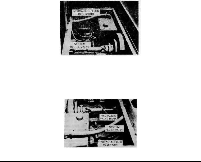
A pressure relief valve attached to the reservoir limits the build-up of system pressure to approximately 1500
P.S.I. any time the free return of fluid is restricted by diversion to a cylinder.
A holding valve in the screed lift system locks the screed hydraulically at any degree of elevation so that it cannot
creep downward due to its weight. Pump pressure is required to unlock this valve and the screed should be lowered with
the engine running fast enough to prevent a jerky descent of the screed due to intermittent "unlocking" of the holding
valve.
A throttle valve in the screed lift system limits the speed of screed descent to a safe rate.
A filter condition gauge on the filter unit in the fluid return line to the reservoir gives a visible indication of the
renewable element's condition. This gauge indicates the relative pressure required to force returning fluid through the 10
micron element. The gauge is only intended for this purpose and does not show paver system operating pressures. (For
recommended gauge readings see "Filter Gauge Readings" paragraph, Item 5) A by-pass feature is included in the filter
assembly so that a clogged element cannot stop the return flow of hydraulic fluid to the reservoir and interrupt system
operation. Important! The paver should not be operated with a clogged filter as an accelerated wearing of vital working
parts may occur and their service life will be shortened.
RH Sub-deck Area - (Walkway Removed)
Figure 3
The components which make up the hydraulic system will perform efficiently and have a long service life if the
following basic service requirements are consistently met.
(2) Fluid Level Check - (Figure 5) Maintain hydraulic fluid supply in reservoir at sight glass level. Fluid capacity
with all lines, components, and reservoir properly filled is approximately 10 gallons.
Use Texamatic Type F automatic transmission fluid only! Do not substitute other fluids. IMPORTANT - All fluid
being added to the reservoir must be completely free of foreign particles and contaminants. All maintenance work
performed on the system must be accomplished without introducing any solid particles which can find their way into
vital operating components.
RH Sub-deck Area - (Walkway Removed)
Figure 4
Page 33