
ENGINE CONTROLS
1. Control Key Switch: The three-position key-operated control switch (See Figure 1) located on the engine
housing instrument panel is a master switch which makes all other engine and paver control switches operative. At the
ON position (vertical) the engine starter solenoid switch and control switches for brakes, lights flashers, feed clutches and
hydraulic solenoids are operative. At the OFF position, nothing electrical is operative except the indicating meters on the
instrument panel. It does not stop engine operation!
The switch is spring loaded for the START position and must be held in that' position to start the engine, in the
manner of automobile engine starting.
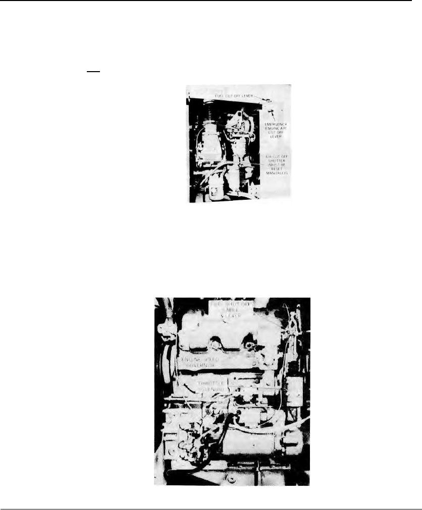
2. Fuel Cut-off Lever
This lever stops the flow of fuel to the engine
injectors to stop operation. It is
located on the side of the engine housing (See
Figure 2).
Figure 2. Diesel Engine - Left Side
3. Emergency Stop Lever
This lever trips an air shutter to the Closed position, thereby cutting off all air flow to the engine fuel system which
brings engine operation to a positive stop. It is located on the side of the engine housing (See Figure 2). IMPORTANT!
When ever the Emergency Stop Lever is used it is necessary that the spring loaded air shutter be reset manually,
otherwise the engine cannot be restarted. The louvered engine cover on the left side must be raised to reach the reset
point. (See Figure 2). If at anytime the engine cannot be started, be sure to see that the air shutter is properly
reset for operation, as the air shutter may have been tripped without the knowledge of the operator.
4. Speed Governor: An adjustable speed governor located on the side of the engine maintains the correct operating
speed at the full throttle setting. (See Figure 3) Correct engine speed is 2000 RPM.
5. Engine Throttle Solenoid: An electric solenoid unit mounted on the engine moves the throttle. mechanism from
Idle to Full Throttle setting. (See Figure 3)
The solenoid is actuated by
a toggle switch on the operator's console.
A spring returns the throttle
to Idle when the solenoid is not energized.
(Refer to the Soft Start
information in the paragraphs covering the
Control Console in Section
8).
Figure 3. Diesel Engine - Right Side
Page 10