
Figure 11. Location Of Clutch For RH Track
PAVER BRAKES
The electro-released brake for each of the two tracks is operated by toggle switch from the paver console. These
switches are labeled "L.H. Track" and "R.H. Track". When a switch is moved to the "Brake" position, the armature plate
on the input shaft of the track gear case is magnetically attracted to the stationary friction plate on the gear case. This
locks the shaft so that no movement of the track can occur. Each track brake operates independent of the other. (See
Figure 12).
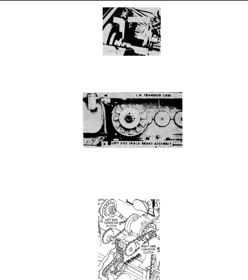
Figure 12. Location Of Brake For LH Track
Depending upon the condition of the 12 VDC Battery, the electric brakes can be released whenever the control key
switch is in the ON position. When all power is OFF, both brakes are locked ON. Complete instructions covering the
care, clearance checking, and repair of the electric brake are contained in the Mechanical Maintenance Section 11.
ASPHALT FEED CLUTCHES (Slat and Screw Conveyors)
The two slat conveyors and the two screw conveyors which combine functions to move asphalt from the hopper to
the area ahead of the trailing screed, are operated by means of two electromagnetic clutches. Each clutch starts or stops
the movement of one side of the feed system (Right hand or Left hand). By chain and sprocket connection, one slat
conveyor and one screw conveyor operate
simultaneously to feed one side. (See
Figure 13) Each clutch is operated by means
of a toggle switch on the operator's
console.
Complete information on the care and
adjustment of electric clutches is
contained in the Mechanical Maintenance
Section 11)
Figure 13. Electric Clutches For Material Conveyors
Page 15