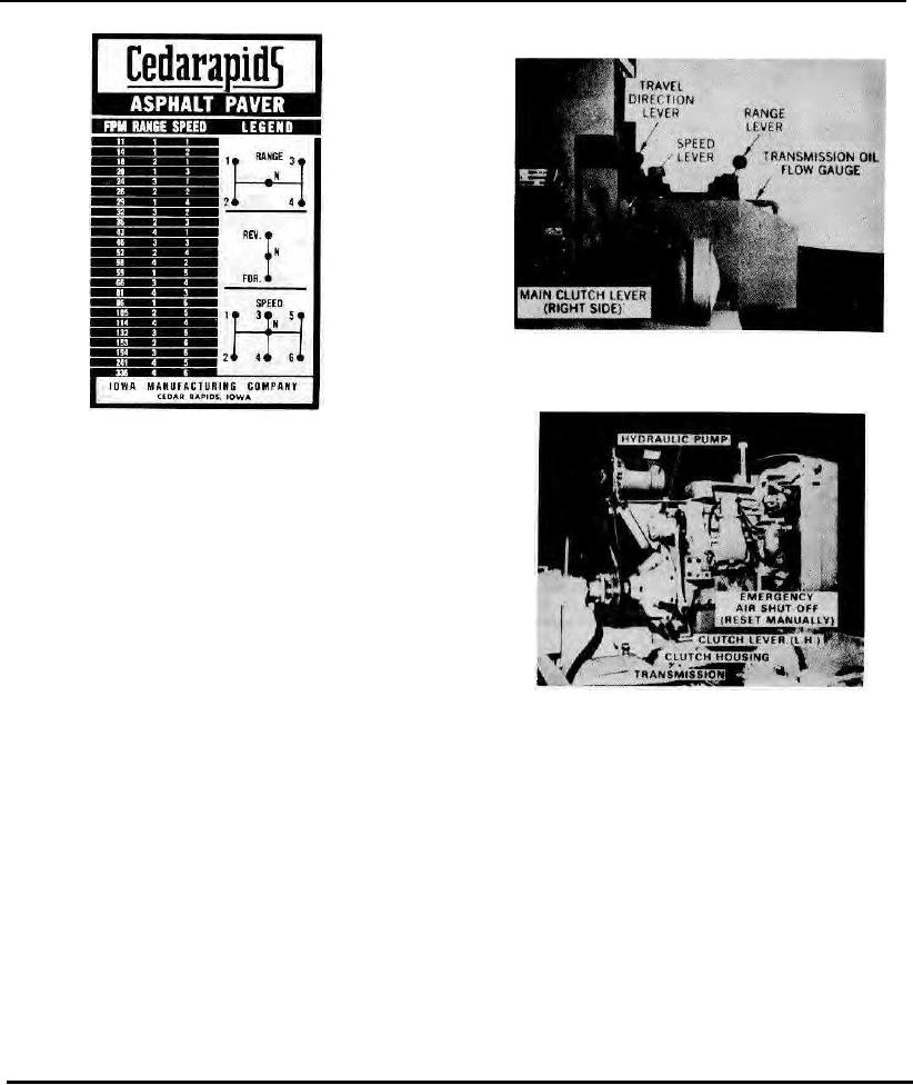
Figure 10. Location
Of
Controls,
Gauge & Limit Switch
Figure 8. 24-Speed Transmission
Selection Plate
(This plate is located on the top of the
engine cover)
MAIN CLUTCH
A main clutch, which is part of the engine assembly, is
manually engaged and disengaged by means of the levers on the
side of the engine (See Figure 9). The clutch lever shaft extends
through the engine housing so that one of the levers is accessible on
each side, for operator convenience.
TRANSMISSION OIL FLOW GAUGE
Indicates that oil is flowing from pump unit to spray nozzle in
the top of the transmission case. Gauge glass will appear clear when
engine is stopped and dark when engine is running and oil is flowing.
(See Figure 10)
Figure 9. Detroit Diesel Engine (Cover
TO SHIFT TRANSMISSION
Removed)
With Engine running:
1. Disengage main clutch. IMPORTANT! The transmission is not synchro mesh. If easy engagement cannot be
achieved, momentarily engage clutch to change gear tooth alignment then disengage clutch and try shifting again.
Never force a shift lever!
2. Check the TRAVEL toggle switches on the operator's console to be sure they are in the BRAKE position.
3. Shift the Direction Lever.
4. Shift the Range Lever.
5. Shift the Speed Lever.
6. Just before moving the paver, engage the Main Clutch.
PAVER TRACK CLUTCHES
The electro magnetic clutch for each of the two track drives is operated by toggle switch from the paver console.
These switches are labeled "L.H. Track" and "R.H. Track". When a switch is moved to the "Travel" position the clutch
discs (Figure 11) for that track are magnetically engaged and that side of the paver moves. When both clutches are
engaged the paver travels in a straight line. An electrical interconnection of clutch and throttle solenoid circuits is used to
produce a "Soft Start" movement of the paver for a smooth take-off after each stop. Complete instructions covering the
care and adjustment of the electric clutches are contained in Mechanical Maintenance Section 11.
Page 14

