
TM 5-3895-385-10
0019
Fill Hydraulic Fluid Reservoir -- Continued.
5. Add hydraulic fluid into reservoir fill neck (Figure 5, Item 7) until fluid level is between 176F and the maximum
indicator (black line) (Figure 4, Item 2) on temperature and liquid sight indicator (Figure 4, Item 1).
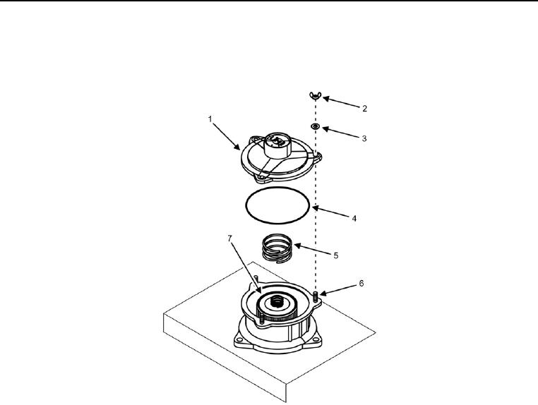
Figure 5. Hydraulic Fluid Reservoir Cap, Spring, and Filter Element.
6. Install spring (Figure 5, Item 5) and O-ring (Figure 5, Item 4) onto filler neck (Figure 5, Item 7).
CAUTION
Maintain even pressure on reservoir cap when installing flat washers and wing nuts. Tighten wing
nuts in sequence around the cap to keep cap level during installation. Failure to comply may
cause damage to equipment.
7. Install reservoir cap (Figure 5, Item 1), three flat washers (Figure 5, Item 3), and wing nuts (Figure 5, Item 2)
onto threaded studs (Figure 5, Item 6), turning wing nuts in alternating sequence until reservoir cap is secure.