
TM 5-3895-385-10
0006
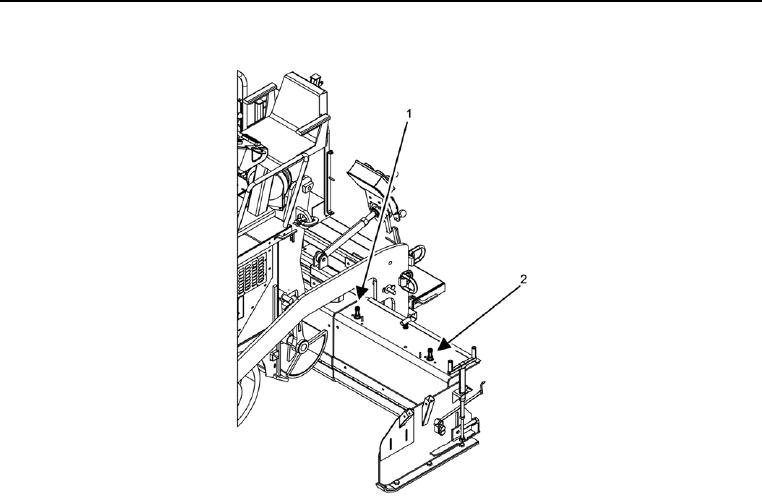
ADJUST SCREED EXTENSION HEIGHT
Figure 24. Vertical Adjustment Screws.
NOTE
Turning outer screed extension vertical adjustment screw clockwise will raise screed extension.
Turning outer screed extension vertical adjustment screw counterclockwise will lower screed
extension.
1. Turn outer screed extension vertical adjustment screw (Figure 24, Item 2) on desired screed extension (left or
right) to reach desired height, taking note of direction of turn and how many turns of screw are being made.
2. Turn the inner screed extension vertical adjustment screw (Figure 24, Item 1) on the same screed extension
in the same direction and the same number of turns as the outer screed extension vertical adjustment screw
(Figure 24, Item 2) was turned.
END OF TASK