TM 5-3895-373-34
B.
ADJUST - Continued.
5.
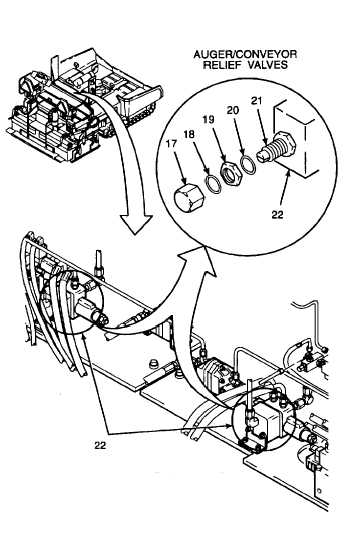
ADJUST
AUGER/CONVEYOR
RELIEF
VALVES.
NOTE
This procedure applies to both left
hand and right hand auger/conveyor
relief valves.
a.
Remove valve cap (17).
CAUTION
Use caution when removing seals
and preformed packings. Do not use
excessive force when removing seals
and preformed packings. Use an o-
ring
tool
to
remove
seals
and
preformed packings.
b.
Use an o-ring tool to remove preformed packing
(18) from valve cap (17).
c.
Remove compression nut (19).
d.
Use an o-ring tool to remove preformed packing
(20) from compression nut (19).
e.
Turn
adjustment
screw
(21)
clockwise
to
increase relief valve setting or counterclockwise
to decrease relief valve setting.
f.
Set auger/conveyor relief valves (22) to 2750 psi
(18 961 kPa).
WARNING
Hydraulic
oil
can
be
moderately
flammable and can be an irritant to
the skin, eyes, and
respiratory
system. Avoid prolonged exposure.
Eye protection and rubber gloves must be worn when
working with hydraulic oil.
g.
Lubricate preformed packings (18 and 20) with
clean hydraulic oil.
h.
Install preformed packing (18) onto valve cap
(17).
i.
Install preformed packing (20) onto compression
nut (19).
CAUTION
Be careful not to damage preformed
packings when sliding over threads.
Sharp edges of threads can cut or
damage
preformed
packings.
Damaged preformed packings will
cause
leakage
and
affect
performance.
j.
Install compression nut (19) onto auger/conveyor
relief valve (22).
k.
Recheck pressure setting.
l.
Install valve cap (17). Tighten valve cap.
GO TO NEXT PAGE
2-687