TM 5-3895-373-34
B.
ADJUST.
NOTE
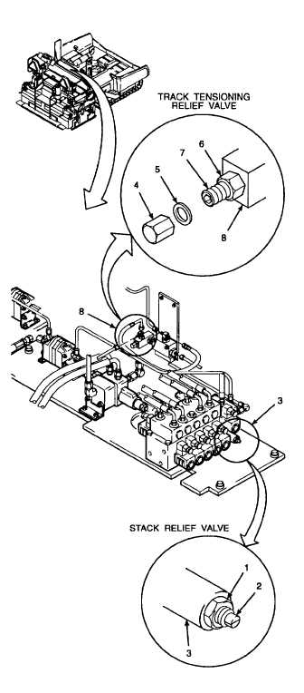
Valves are illustrated as located on
the paving machine for on-machine
adjustment.
Valve
settings
are
measured using hydraulic systems
test and repair tool outfit. Refer to
TM 9-4940468-14 for procedures.
Before adjusting a valve installed on
the machine, you should perform
equipment setup per step A.2.
1.
ADJUST STACK RELIEF VALVE.
a.
Loosen jam nut (1).
b.
Turn adjustment screw (2) clockwise to increase
relief valve setting
or
counterclockwise
to
decrease relief valve setting.
c.
Set stack valve safety relief valve (3) to 2500 psi
(17 238 kPa).
d.
Tighten jam nut (1). Ensure adjustment screw
(2) does not turn while tightening jam nut.
e.
Recheck pressure setting.
2.
ADJUST TRACK TENSIONING RELIEF VALVE.
NOTE
Before adjusting track tensioning
relief pressure while the valve is in
the machine, loosen hex nut and turn
adjustment screw on track tensioning
unloading valve clockwise until it is
all the way in. Refer to step 3.b.
a.
Remove cap nut (4) and flat washer (5).
b.
Loosen hex nut (6).
c.
Turn adjusting screw (7) clockwise to increase
relief pressure setting or counterclockwise to
decrease relief setting. Ensure stack valve relief
pressure is set to 2500 psi (17 238 kPa) per step
l.c.
d.
Set track tensioning relief valve (8) to 1800 psi
(12 411 kPa).
f.
Recheck pressure setting.
e.
Tighten hex nut (6). Ensure adjusting screw (7)
does not turn while tightening hex nut. g. Install
flat washer (5) and cap nut (4). Tighten cap nut.
GO TO NEXT PAGE
2-685