TM 5-3895-373-20
1.12.7. Screed Burner System. A screed burner
system is located in each of the main and extension
screeds. The burner systems are used to heat screed
plates to approximately the same temperature as the
paving material. Heating the screed plates prevents hot
aggregate mixtures from cooling and sticking to the
bottom of the screed. The left burner systems are
controlled from the left screed control panel. The right
burner systems are controlled from the right screed
control panel. The main screed burner system
components are as follows:
a.
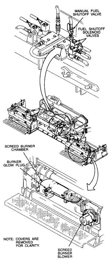
Screed Burner Chambers. Separate burner
chambers are located on the left and right sides of the
main screed and on the left and right extension screeds.
A fuel spray nozzle and forced air duct are located on the
input side of the burner chamber. When burner fuel flow
is turned on, the spray nozzle atomizes the incoming fuel
and the fuel is ignited by a 12 VDC glow plug. In normal
use, fuel combustion continues until the fuel flow is shut
off.
b.
Screed Burner Blowers. The burner blowers
consist of a fan rotor mounted on the shaft of a 12 VDC
motor. The blowers force combustion air into the burner
chambers for increased combustion efficiency. The
blower motors are controlled from both left and right
screed control panels.
c.
Manual Fuel Shutoff Valves. Manual fuel shutoff
valves are used to turn fuel flow on and off to the burner
chambers. The paving machine is equipped with four
solenoid controlled valves controlling fuel flow to each
screed burner. The +12 VDC solenoid valves are
activated by switches on the screed control panels.
The manual fuel shutoff valve provides a backup shutoff
capability in case of solenoid valve failure.
1-12