TM 5-3895-371-24 & P
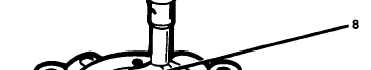
Figure 3-49. Checking Charge Pump Clearance.
(31)
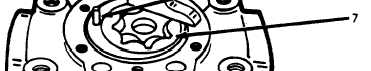
Install new O-ring (5, fig. 3-4) to outside of spacer assembly (7). The direction of pump
rotation is Indicated by an arrow cast on the charge pump cover. To operate properly, the plate (4)
must be installed to correspond with the porting in the pump cover (3). Install plate over roll pin in
spacer assembly (7). (Refer to fig. 3-50.)
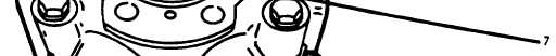
Figure 3-50. Charge Pump Upper Valve Plate.
(32)
From pump cover (3, fig. 3-4), remove all shims for testing.
3-42