
TM 5-3895-356-14&P
THE BASIC DYNAPOWER TRANSMISSION SYSTEM
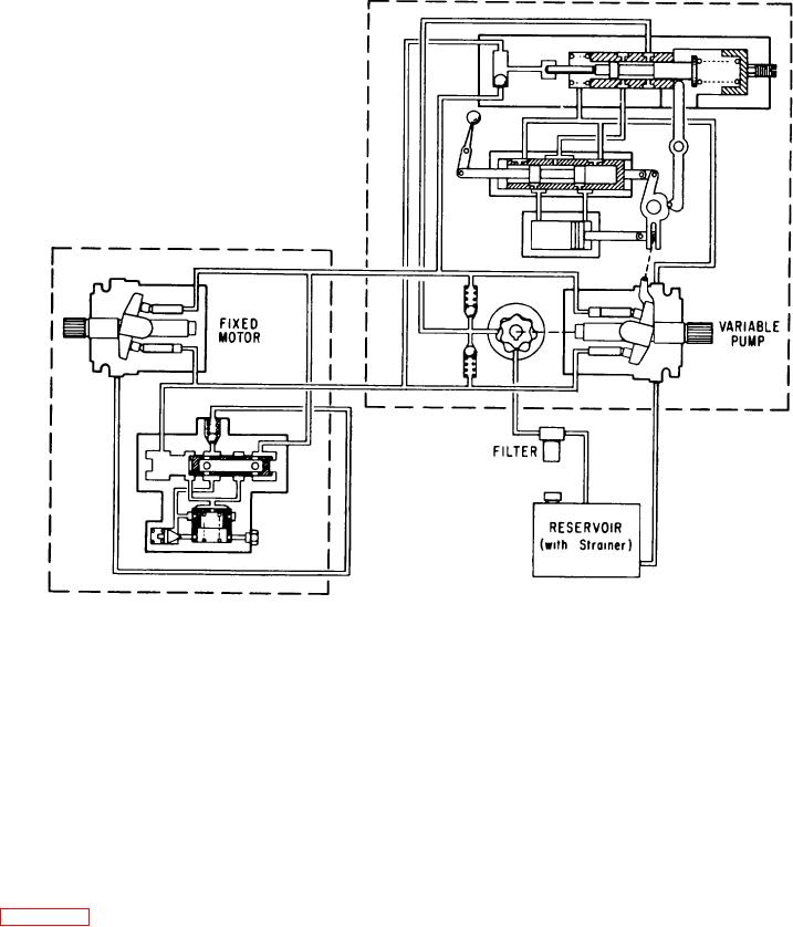
Figure 102.
Dynapower variable pump, fixed motor schematic.
The pump may be driven by any conventional source of
power: diesel, gasoline or electric. The hydraulic motor
A. Description
may be of fixed or variable displacement. When a
variable motor is used, it would also require its own
The Dynapower hydrostatic transmission uses a
control unit. However, a fixed-displacement hydraulic
closed circuit hydraulic system capable of "over center"
motor is referred to in this manual unless otherwise
operation. The inlet and discharge ports of a variable-
noted.
displacement, axial-piston pump are connected to the
discharge and inlet ports of an axial-piston motor (fixed
Other components of the system are: a filter and
or variable) by hose or tubing. The two main hoses must
reservior system, the fluid itself, a cooler (if required), the
be of high pressure type, capable of withstanding
connection from the hydraulic pump to the power source,
working pressures up to 5000 PSI; all other hoses can
the connection from the hydraulic motor to the output
be of low pressure type.
and the linkage to the pump control (and motor control, if
a variable motor is used).
See Figure 101
83