
TM 5-3895-356-14&P
BURNER ASSEMBLY
BURNER ASSEMBLY DESCRIPTION
The burner assembly consists of the fuel lines and
valves, the air lines and valves, two atomizing burners
and combustion chambers. Each burner contains a
body, an inner air nozzle, an outer air nozzle and an oil
injector tube. The injector tube is mounted inside the
outer air nozzle. Air from the blower enters the inner air
nozzle through slots which give it a rotary motion. The oil
tube is positioned so that the tip is at the point where the
rotating air is at its maximum velocity and breaks up the
oil and causes it to atomize. The resulting mixture
leaves the end of the inner nozzle through a constricted
opening where it is joined at a 450 angle by a second
stream of air from the outer air nozzle. This produces
further atomization of the fuel oil and gives direction and
velocity to the flame. The air and fuel lines are provided
with relief valves and controls to regulate the flame.
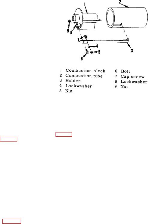
Figure 82. Combustion Tubes
BURNER ASSEMBLY REMOVAL
BURNER DISASSEMBLY
a. Burner Removal
a. Remove the street elbows from the valve bodies.
(1) Remove the machine screw (34) securing
(10, Fig. 83).
the flexible air hose (35, (Fig. 83) to the
manifold (27).
b. Remove the handwheel (3).
(2) Remove the air hose from the blower.
c. Remove the packing nut (4) and the valve stem
(7) from the valve body. Remove the packing and the
(3) Remove the two tubes that secure the fuel
washer from the valve stem.
tubes to the elbows.
d. Remove the valve bodies (8) from the strainers
(4) Remove the fuel lines.
(9).
(5) Remove handwheel and valve assemblies.
e. Remove the two bushings (22) from the inner air
nozzles (17) and remove the tips (20) from the injector
(6) Remove the burner assemblies.
tubes (21) and the tubes from the bushings.
b. Ignition Tile Removal
f. Remove the two plates (18) and the inner
nozzles.
(1) Remove the three screws (Fig. 82) and
remove the two cover plates and the two
g. Remove the two stops (15) from the nozzle
tiles.
bodies (16).
h. Remove the two stop plates (13) from the nozzle
bodies.
59