
ATTACHMENT OF A.C. TAP TO D.C. GENERATOR
The hourmeter-tachometer on the instrument panel which indicates engine speed and records the
number of hours of engine operation derives its tachometer function from an alternating current (A.C.) tap
on the 12 V.D.C. generator. The A.C. tap must be applied to a diode lead on the 12 V.D.C. generator,
using an effective heat sink to prevent destruction of the diode.
In the event that a new 12 V.D.C. generator is installed, transfer the A.C. tap kit from the old unit to the
new in the following manner.
1.
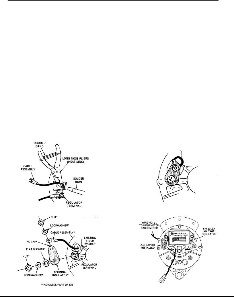
Form tight loop on stripped end of cable assembly and slip over lead of diode as shown in Figure 14.
2.
Solder-cable assembly to diode lead.
CAUTION
Use long nose pliers as heat sink to prevent damage to diode. (See Figure 14)
3. Remove all nuts and washers (and connectingwires, if generator is already installed) from
insulating fiber washer on terminal.
4. Mount terminal insulator to REGULATOR TERMINAL and secure with nut, lockwasher and flat washer
(supplied in Kit). Align terminal insulator as shown in Figure 16. Reconnect all connecting wires to terminal.
5. Connect terminal of newly soldered cable assembly to A.C.
tap on terminal insulator and secure with
lockwasher and nut provided.
6.
Use keps nut removed from generator on REGULATOR TERMINAL of generator. Leave A.C. tap.
Figure 16
Figure 14
Figure 17
Figure 15
Page 22