
Engine Tune-Up
The setting is too tight if, when moving the speed control
No. 3L injector rack control lever down as shown in Fig.
lever from the no-speed to the maximum speed
3 until a slight movement of the control tube lever is
position, the injector rack becomes tight before the
observed or a step-up in effort to turn the screw driver is
speed control lever reaches the end of its travel (as
noted. This will place the No. 3L injector in the full-fuel
determined by the stop under the governor cover).
position. Turn down the outer adjusting screw until it
bottoms lightly on the injector control tube. Then
This will result in a step-up in effort required to move the
alternately tighten both the inner and outer adjusting
speed control lever to the end of its travel. To correct
screws.
this condition, back off the inner adjusting screw slightly
and tighten the outer adjusting screw slightly.
NOTE: Overtightening of the injector rack control
lever adjusting screws during installation or
8. Remove the clevis pin from the fuel rod and the left
adjustment can result in damage to the injector
bank injector control tube lever.
control tube. The recommended torque of the
9. Insert the clevis pin in the fuel rod and the right
adjusting screws is 24-36 in-lbs (3-4 Nm).
cylinder bank injector control tube lever and position the
IMPORTANT: The above step should result in
No. 3R injector rack control lever as previously outlined
placing the governor linkage and control tube
in Step 6 for the No. 3L injector rack control lever.
assembly in the same position that they will attain
10. Insert the clevis pin in the fuel rod and the left
while the engine is running at full-load.
cylinder bank injector control tube lever. Repeat the
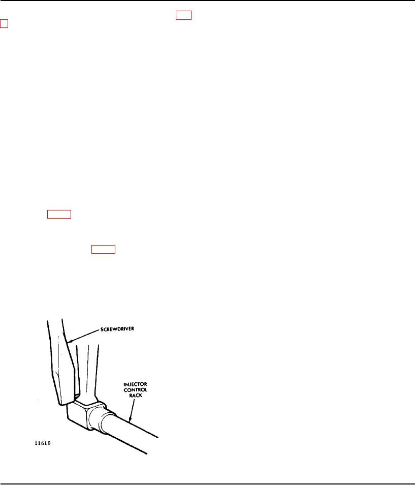
7. To be sure of the proper rack adjustment, hold the
check on the 3L and 3R injector rack control levers as
speed control lever in the maximum speed position and
outlined in Step 7. Check for and eliminate any
press down on the injector rack with a screw driver or
deflection which may occur at the bend in the fuel rod
finger tip and note "rotating" movement of the injector
where it enters the cylinder head.
control rack (Fig. 4) when the speed control lever is in
11. To adjust the remaining injector rack control levers,
the maximum speed position. Hold the speed control
remove the clevis pin from the fuel rods and the injector
lever in the maximum speed position and, using a screw
control tube levers, hold the injector control racks in the
driver, press downward on the injector control rack. The
full-fuel position by means of the lever on the end of the
rack should tilt downward (Fig. 5) and when the pressure
control tube, and proceed as follows:
of the screw driver is released, the control rack should
"spring" back upward.
a. Turn down the inner adjusting screw of the injector
rack control lever until the screw bottoms (injector
If the rack does not return to its original position, it is too
control rack in the full-fuel position).
loose. To correct this condition, back off the outer
adjusting screw slightly and tighten the inner adjusting
b. Turn down the outer adjusting screw of the injector
screw slightly.
rack control lever until it bottoms on the injector
control tube.
c.
While still holding the control tube lever in the full-
fuel position, adjust the inner and outer adjusting
screws to obtain the same condition as outlined in
Step 7. Tighten the screws.
CAUTION: Once the No. 3L and No. 3R injector
rack control levers are adjusted. do not try to alter
their settings. All adjustments are made on the
remaining control racks.
NOTE: Overtightening of the injector rack control
tube lever adjusting screws during installation or
adjustment can result in damage to the injector
control tube. The recommended
Fig. 5 - Checking Injector Control Rack
Spring
Page 88