
Engine Tune-Up
engine. Cylinders are numbered starting at the front of
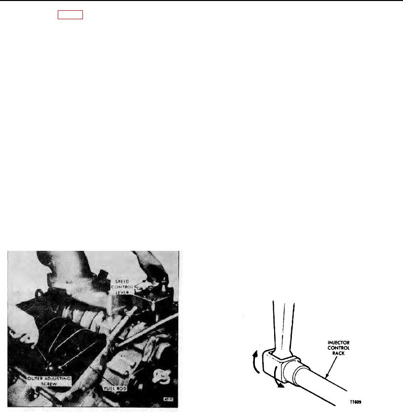
adjusting screw (Fig. 2). If the setting is correct, the
the engine on each cylinder bank. Adjust the No. 3L
.0015" movement can be seen by placing a few drops of
injector rack control lever first to establish a guide for
oil into the governor gap and pressing a screw driver
adjusting the remaining injector rack control levers.
against the gap adjusting screw. Movement of the cap
toward the plunger will force the oil from the gap in the
1. Disconnect any linkage attached to the speed control
form of a small bead.
lever.
7. Hold the gap adjusting screw and tighten the lock
2. Turn the idle speed adjusting screw until 1/2" of the
nut.
threads (12-14 threads) project from the lock nut when
the nut is against the high-speed plunger.
8. Recheck the gap and readjust if necessary.
9. Stop the engine and, using a new gasket, install the
CAUTION: A false fuel rack setting may result if
governor cover.
the idle speed adjusting screw is not backed out as
noted above.
Position Injector Rack Control Levers
NOTE: This adjustment lowers the tension of the
The position of the injector racks must be correctly set in
low-speed spring so it can be easily compressed.
relation to the governor. Their position determines the
This permits closing the low speed gap without
amount of fuel injected into each cylinder and ensures
bending the fuel rods or causing the yield
equal distribution of the load. Properly positioned
mechanism springs to yield or stretch.
injector rack control levers with the engine at full-load
will result in the following:
3. Back out the buffer screw approximately 5/8", if it
has not already been done.
1. Speed control lever at the maximum speed position.
4. Remove the clevis pin from the fuel rod and the right
2. Governor low-speed gap closed.
cylinder bank injector control tube lever.
3. High-speed spring plunger on the seat in the
5. Loosen all of the inner and outer injector rack control
governor control housing.
lever adjusting screws on both injector control tubes. Be
4. Injector fuel control racks in the full-fuel position.
sure all of the injector rack control levers are free on the
injector control tubes.
6. Move the speed control lever to the maximum speed
position; hold it in that position with light finger pressure.
Turn the inner adjusting screw on the
Fig. 4 Checking Rotating Movement of
Fig. 3 - Positioning No. 3L Injector Rack
Injector Control Rack
Control Lever
The letters R or L indicate the injector location in the
right or left cylinder bank, viewed from the rear of the
Page 87