
Engine Equipment
Clutch
Hand Lever
Pressure
Torque
Diameter
Length
PSI
kPa
Ib-ft
Nm
56-63
76-85
55
379
15 1/2"
8"
87-94
113-127
80
552
15 1/2"
10"
129
175
100
689
15 3/8"
*11 1/2"
112-120 152-163
105
724
20"
11 1/2"
*Twin Disc Clutch
TABLE 1
clutch release shaft (Fig. 11), is obtained as shown in Table 1.
When properly adjusted, the approximate pressure required at the outer end of the hand lever to engage the various
diameter clutches is shown in the table. These specifications apply only with the hand lever which is furnished with the
power take-off.
A suitable spring scale may be used to check the pounds pressure required to engage the clutch. However, a more
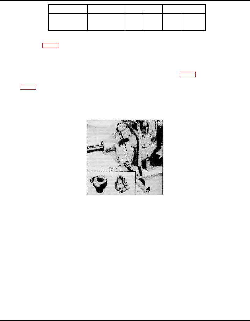
accurate method of checking the clutch adjustment is with a torque wrench as shown in Fig. 11.
To fabricate an adapter, saw the serrated end off of a clutch hand lever and weld a 1-1/8" nut (across the hex) on it as
shown in Fig. 11. Then saw a slot through the nut.
When checking the clutch adjustment with a torque wrench, engage the clutch slowly and note the amount of torque
immediately before the clutch engages (goes over center). The specified torque is shown in Table 1.
CAUTION: The thrust load on the bronze clutch release bearing should be kept at an absolute minimum.
Therefore, the hand lever should be positioned on the shaft as near the 12 o'clock or 6 o'clock position as
possible. The 9 and 3 o'clock positions are to be avoided.
Fig. 11 - Checking Clutch Adjustment with a Torque Wrench and Adapter
Make a final clutch adjustment with the engine running as follows:
1.
Start the engine and operate it at idling speed (approximately 500 rpm) with the clutch disengaged. The speed will
be sufficient to move the segments out to the operating position.
2.
Check the pressure required to engage the clutch. The engagement pressure should be the same as that following
the adjustment. If the clutch engages at a lower pressure, the adjustment was probably made against the unworn portion
of the facing.
3.
Stop the engine and readjust the clutch, making sure all disc segments are properly positioned.
Install the
inspection hole cover.
TORQMATIC CONVERTERS
The Torqmatic converter is a self contained unit which transfers and multiplies the torque of the prime mover. This unit
transmits the power through the action of oil instead of through gears and in addition to multiplying the torque also acts
as a fluid coupling between the engine and the equipment to be powered. The converter will automatically adjust the
output torque to load requirements.
There are various combinations of Torqmatic converters with features such as: an automotive or industrial flange on the
shaft, a hydraulically operated lock-up clutch, a manual input disconnect clutch, and an accessory drive for either a
governor or tachometer.
Check the oil level daily. If the converter is equipped with an input disconnect clutch, additional checks and
service will be necessary daily or at intervals determined by the type of operation.
Adjust the disconnect clutches as outlined under power take-off clutch adjustment.
Contact an authorized Detroit Diesel Allison Service Outlet for service on Torqmatic converters.
Page 45