
TM 5-3895-385-10
0025
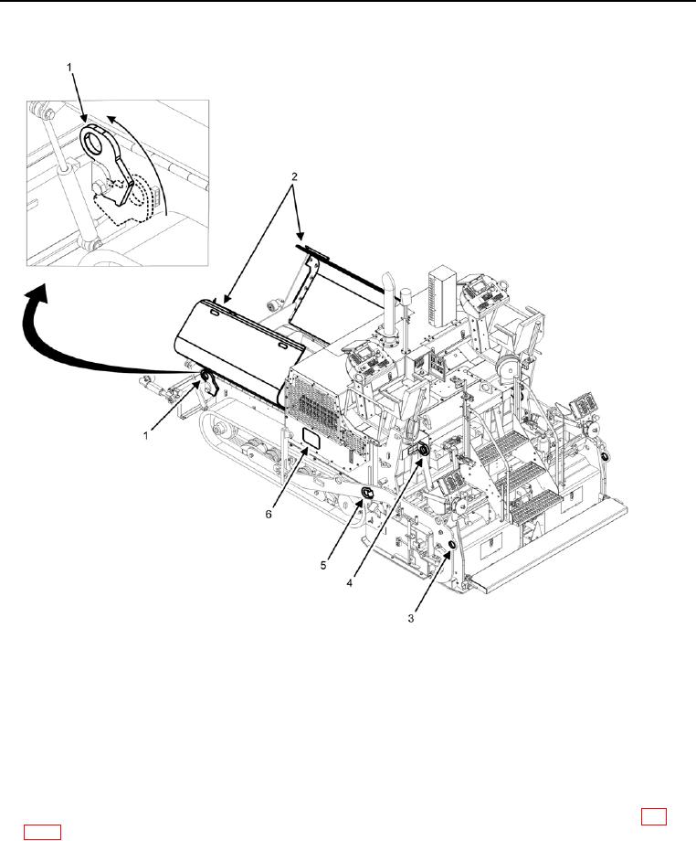
BMPM TIE DOWN POINTS
Figure 3. BMPM Tie Down Points.
1. The front tie down points (Figure 3, Item 1) are located under the left and right hopper wings (Figure 3, Item
2). Hopper wings must be fully closed and tie down points must be brought forward before use.
2. The forward screed arm tie down points (Figure 3, Item 5) are located on the left and right forward screed
arms.
3. The rear screed arm tie down points (Figure 3, Item 3) are located on the left and right rear screed arms.
4. The rear operator platform tie down points (Figure 3, Item 4) are located just behind the operator platform.
5. The lifting and tie down shipping data plate (Figure 3, Item 6) is located on the left side of the BMPM (WP
END OF TASK