TM 5-3895-373-20
REFERENCE INFORMATION
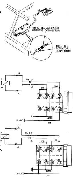
ENGINE THROTTLE CONTROL CIRCUIT
Refer to TM 5-3895-373-10 for engine starting and equipment operating procedures. Refer to paragraph 2.10 for
connecting and disconnecting STE/ICE-R test set to DCA.
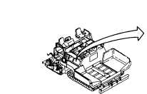
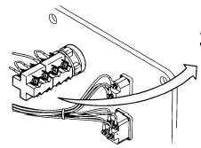
Open right access door per TM 5-3895-373-10
to gain access to throttle actuator.
Refer to the electrical system diagram at the end
of the manual for equipment wiring details.
12 vdc control voltage should be at harness
connector terminal with throttle control switch in
either IDLE or MAX position.
If paving machine starts, circuit breaker CB1 is
conducting +12 vdc to the neutral start circuit.
Thereby, if throttle control switch circuit loses
voltage, problem must be throttle actuator,
switch, or open wiring.
Holding engine throttle control switch in IDLE
position provides 12 vdc to drive the actuator
motor. In MAX position, polarity to the actuator
motor is reversed.
Refer to paragraph 7.21 for harness and lead
wire repair.
Remove gauge panel per paragraph 7.6 to gain
access to throttle control switch terminals.
2-237