TM 5-3895-373-20
REFERENCE INFORMATION
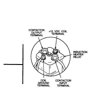
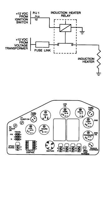
COLD START CONTROL CIRCUIT
+12 vdc voltage at ignition switch terminal #1 is from the
+12 vdc terminal of the voltage transformer. The voltage
is routed through the 80 amp breaker, circuit breaker
CB8, and the emergency stop switch circuit.
Refer to the electrical system diagram at the end of the
manual for equipment wiring details.
Remove gauge panel per paragraph 7.6 to gain access
to ignition switch terminals.
Turning ignition switch to the preheat position should
place the +12 vdc supply voltage at output terminal #5 of
ignition switch.
Refer to paragraph 7.21 for harness and lead wire repair.
After completing diagnostic checks, close rear top left
access door per TM 5-3895-373-10.
Install gauge panel per paragraph 7.6. Install engine
access cover per paragraph 2.22.
2-233