TM 5-3895-373-20
REFERENCE INFORMATION
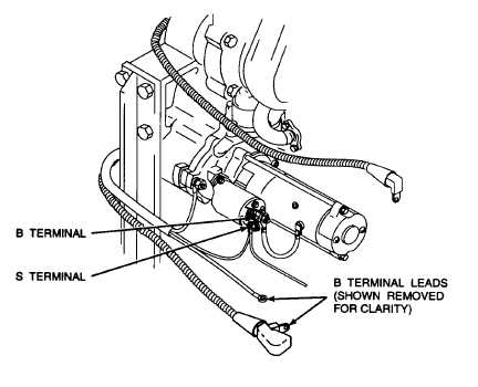
BATTERY/STARTER CIRCUIT
Open engine access cover per paragraph 2.22
to gain access to starter.
STARTER VOLTAGE - STE/ICE-R TEST 68
DESCRIPTION
TEST PROCEDURES
Measures the voltage present at the starter positive (B) terminal.
1.
Set TEST SELECT switches to 68,.
DCA Test Pins: T and W
2.
Turn ignition switch to START position for 10
seconds
Measurement Range: 0 to 32 Vdc
3.
Press and release TEST button.
PRE-TEST PROCEDURES
Run confidence test per TM 9-4910-571-12&P.
4.
Observe displayed value. Displayed values are
in volts. If .9.9.9.9 is displayed, voltage is not
within test range Expected minimum display
value is 17 volts.
POSSIBLE ERROR MESSAGES
None
STARTER SOLENOID VOLTAGE - STE/ICE-R TEST 70
DESCRIPTION
TEST PROCEDURES
Measures the voltage present at the starter solenoid ’S’ terminal.
1.
Set TEST SELECT switches to 70.
DCA Test Pins: S and W 373-10
Measurement Range: 0 to 32 Vdc
2.
Turn ignition switch to START position per TM 5-
3895-373-10.
3.
Press and release TEST button.
PRE-TEST PROCEDURES
Run confidence test per TM 9-4910-571-12&P.
4.
Observe displayed value. Displayed values are
in volts. If .9.9.9.9 is displayed, voltage is not
within test
range. Expected minimum display value is 18
volts.
POSSIBLE ERROR MESSAGES
None
2-125