TM 5-3895-373-20
1.11.
CHARACTERISTICS,
CAPABILITIES,
AND
DATA.
The paving machine is a turbosupercharged, 4-cylinder,
diesel powered, hydraulically driven tracked vehicle.
The engine is coupled to a dual main pump drive
gearbox which drives two propulsion pumps in tandem
with two auxiliary pumps and one auxiliary vibration
pump. The propulsion pumps supply hydraulic pressure
to the track drive motors. The auxiliary hydraulic pumps
are used to operate all controls and cylinder drive
functions.
Control handles on the operator control panel control
each track drive motor located on the undercarriage of
the paving machine. Paving speed is from 0 to 135 fpm
(O to 41 mpm) with travel speed (switch selected) of 0 to
3.2 mph (O to 5, 2 kph). Hydraulic cylinders
automatically maintain tension on the 12-inch wide steel
track pad. A high wear-resistant rubber pad is attached
to each track pad. Spring applied hydraulically released
disc brakes are located between the hydraulic drive
motors and torque hubs. In the event that hydraulic
pressure or electrical power is lost, the brakes are
automatically applied.
Push rollers are located in front of the material hopper
and are designed to ride against the rear wheels of the
paving material haul truck. The push rollers allow the
paving machine to push the haul truck forward, while
continuing to receive material into the hopper and spread
the paving material at the same time. Hopper wings are
hydraulically raised and lowered from the operator
control console. Dual slat conveyors move the paving
material from the hopper to the auger, and are
independently controlled from the operator control
console. Two electric actuators control flow gates that
meter the amount of material conveyed to the augers.
Two 12-inch (304 mm) augers spread the paving
material in front of the screed.
Four diesel fuel-fired burners are located on the screed.
The burners heat the screed plates to approximately
300°F (150°C) to prevent paving material from sticking to
the screed plates. The screed is hydraulically
extendable from 8 to 14 feet (2, 4 to 4, 3 m) and can be
extended further to 16 feet (4, 9 m) with bolt-on screed
and auger extensions. Mechanical adjustments on the
screed control the thickness, slope, and crown of the
paving material. The screed vibrator provides the initial
compaction of the paving material. The amount of
compaction is controlled by the frequency and amplitude
of vibration. Vibration is controlled by the screed
vibration control valve, located underneath the operator
platform on the rear tractor bulkhead.
1.12.
LOCATION AND DESCRIPTION OF MAJOR
COMPONENTS.
The following provides the location and description of
major paving machine components maintained by the
organizational maintenance activity.
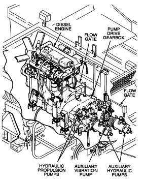
1.12.1. Engine
Compartment.
The
engine
compartment houses the paving machine drive system
and hydraulic power components, air cleaner, filters,
radiator, hydraulic oil cooler, exhaust system, and flow
gates. These components are described as follows:
a. Drive System and Hydraulic Power. The paving
machine drive system includes a turbosupercharged
diesel engine with a pump drive gearbox adapted to the
engine flywheel. Directly coupled to the gearbox drives
are two main hydraulic propulsion pumps. The
propulsion pumps provide hydraulic power to the left and
right track drive motors. Two auxiliary hydraulic pumps,
and one vibration pump are connected to the propulsion
pumps in tandem. These pumps provide hydraulic
power to non-propulsion hydraulic functions needed to
operate the paving machine.
1-3