TM 5-3895-371-24 & P
TA 075965
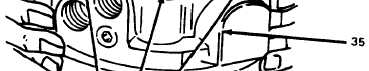
Figure 3-92. Installing Motor Cover.
(24)
If previously removed, install two plugs (38, fig. 3-93) with new O-rings (37).
(25)
Install shuttle valve assembly (39) in cover (35). Check for free movement from side to
side. If any tightness is felt, remove any nicks or burn with 500 grit emery. It is essential to the proper
operation of the relief valve stem that the shuttle valve operate freely. Install shuttle plugs (40, fig. 3-
60) with new O-rings (31).
TA 075966
Figure 3-93. Installing Shuttle Valve.
3-76