TM 5-3895-371-24 & P
(12)
Install piston assemblies (31, fig. 3-4) in return plate (32). Used pistons must be so
positioned in the return plate to allow placement of pistons in their respective block assembly bores as
described.
(13)
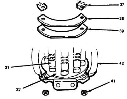
If return plate assembly, consisting of two spacers (41), bearing plate (39), clip (38),
two new locktabs (37), and two capscrews (36), was disassembled; reassemble. Do not tighten cap-
screws (36).
(14)
Spread a light film of oil over the surface of the wear plate (34) and slide piston (31)
return plate (32) assembly into place.
(15)
(39), clip
Assemble second of two return plate assemblies. Install two spacers (41), bearing plate
(38), two new lock tabs (37), and two capscrews (36). (Refer to fig. 3-37.) Torque four cap-
screws (36, fig. 3-4) to 13 lb-ft (17.6 N-m). Check clearance between each piston shoe and wear plate
surface. Clearance should not be less than 0.003 or more than 0.007 in. Clearance of 0.0015 to 0.003
am acceptable only if the rotating group spins freely by hand with no binding or tight spots. Turn up
locktabs (37).
Figure 3-37. Return Plate Assembly.
3-33


