TM 5-3895-371-24 & P
(8)
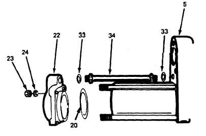
Carefully, remove four hex nuts (23, fig. 3-14) and lockwashers (24). Lift off cylinder
cover (22) including O-ring (20). Pull transfer tube (34) and two O-rings (33) from the seat in either the
housing (5) or the cylinder cover (22). (Refer to fig. 3-10.)
Figure 3-14. Cylinder Cover with Transfer Tube.
(9)
Remove tube (26, fig. 3-15) with plunger assembly (30), from housing (5). Slide the
plunger assembly (30) from tube (26) and remove two O-rings (20), one from the piston assembly (27)
and one from the housing (5). (Refer to fig. 3-10.)
Figure 3-15. Cylinder with Servo Plunger.
3-16