TM 5-3895-356-14&P
BURNER FUEL PUMP
BURNER FUEL PUMP DESCRIPTION
b. Remove the gear (12) from the head and
The burner fuel pump is mounted on the blower housing
remove the impeller and shaft (11) from the housing
and is blower shaft driven through a coupling. The pump
(10).
consists of a housing, rotor with shaft, idler head with pin
and idler. The idler rotates on an eccentric pin on the
c. Remove the packing nut (4), spring (5), and the
head which is bolted on the housing. The rotor with shaft
retainer (6) from the pump housing (10).
is mounted in the housing so the rotor engages the idler.
The opposite end of the shaft is mounted with packing,
d. Remove the packing (7 and 8), the sleeve
packing gland, spring and nut. The rotor and idler
bearing (9) from the housing.
creates a pumping action which sucks oil into the intake
part and expels it through the outlet port.
BURNER FUEL PUMP REMOVAL
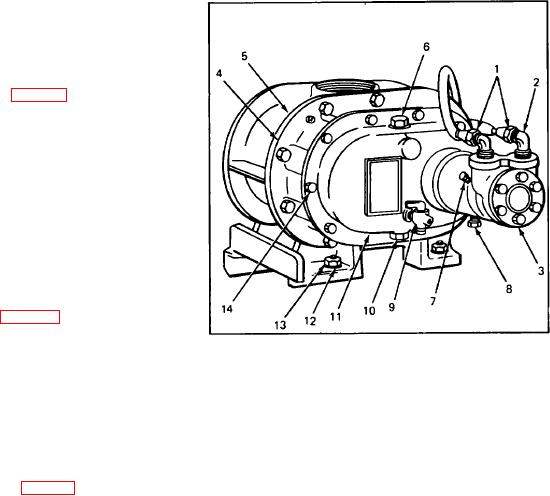
a. Remove the twn tube nuts (1, Fig. 89) from the
elbows (2) and remove the drain plug (8).
b. Remove the drain plug (10) from the gear
housing (11) and drain the oil.
c. Remove the ten cap screws (14) securing the
gear housing (11) to the blower (5). Remove the gear
housing and the gasket (4) from the blower.
d. Remove the two setscrews (7) that secure the
pump assembly to the gear housing.
e. Remove the setscrews (2, fig. 90) from the
coupling (3) and the key (16) from the shaft (11).
Fig. 89. Burner Blower and Fuel Pump
f. Remove the assembly from the gear housing.
1
Tube nut
8
Drain plug
2
Adapter
9
Level cock
3
Burner fuel pump
10
Drain plug
4
Gasket
11
Gear housing
BURNER FUEL PUMP DISASSEMBLY
5
Blower
12
Lockwasher
6
Plug
13
Nut
a. Remove the six cap screws (15, fig. 90) securing
7
Set screw
14
Cap screw
the head (14) to the pump housing (10). Remove the
head and gasket (13) from the housing.
67

