
TM 5-3895-356-14&P
POWER CONTROLS AND COMPONENTS
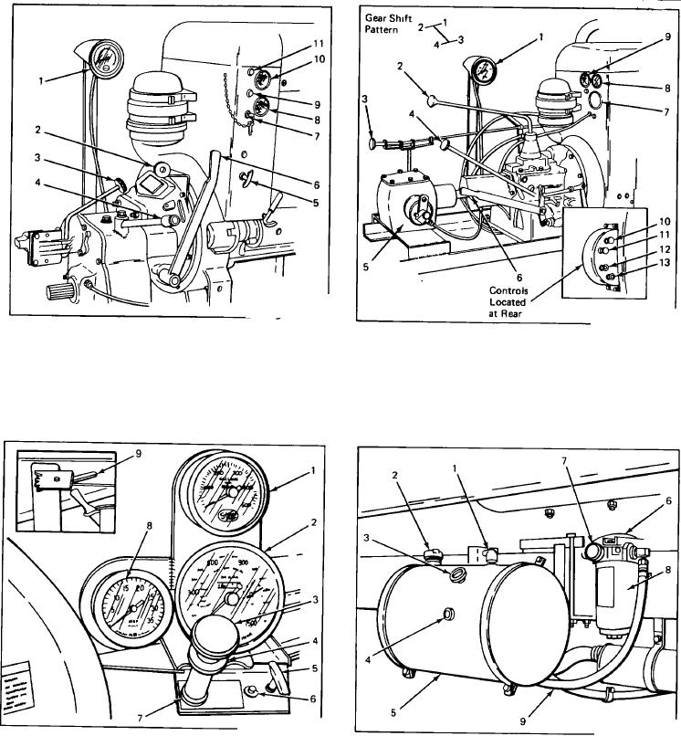
Figure 5
Figure 6
1.
Pump Tachometer (G.P.M.)
6.
Main Clutch Lever
1.
Pump Tachometer (G.P.M.)
7.
Generator Indicator Light
2.
Governor Control
7.
Ignition Switch
2.
Gear Shift
8.
Temperature Gauge
3.
Fuel Pump and/or Blower
8.
Temperature Gauge
3.
Governor Control
9.
Oil Pressure Gauge
Clutch Lever
9.
Starter Switch
4.
Fuel Pump and/or Blower
10.
Starter Switch
4.
Gear Shift
10.
Oil Pressure Gauge
Clutch lever
11.
Ignition Switch
5.
Choke
11.
Generator Indicator Light
5. Angle Drive
12.
Choke
6. Main Clutch Lever
13.
Throttle
Figure 7
Figure 8
HYDROSTATIC RESERVOIR AND FILTER
HYDROSTATIC CONTROLS (CAB MOUNTED)
1. Air Vent
5. Hydraulic Reservoir
1.
Pump Tachometer (G P M ) 6. High Temperature Light
2. Fill Cap
6. Hydraulic Line Filter to Pump
2.
Recording Bitumeter
7. Lock Ring
3. Hydraulic Oil0 Temperature
7. Vacuum Gauge
3.
Main Hydraulic Control
8. P T O Tachometer R P M
Gauge
8. Filter
4.
Fine Control Knob
(Automatic Transmissions Only)
4. Oil Level Sight Glass
9. Hydraulic Line Reservoir to
5.
Override Control
9. Hydrostatic Rear Override Control
Filter
5