
Engine Tune-Up
Fig. 3 - Positioning No. 3L Injector Rack Control Lever
2.
Stop lever in the RUN position.
3.
Injector fuel control racks in the full-fuel position.
The letters R or L indicate the injector location in the right or left cylinder bank, viewed from the rear of the engine.
Cylinders are numbered starting at the front of the engine on each cylinder bank. Adjust the No. 3L injector rack control
lever first to establish a guide for adjusting the remaining levers.
1.
Remove the clevis pin from the fuel rod and the right cylinder bank injector control tube lever.
2.
Loosen all of the inner and outer injector rack control lever adjusting screws on both injector control tubes. Be sure
all of the injector rack control levers are free on the injector control tubes.
3.
Move the speed control lever to the maximum speed position.
4.
Move the stop lever to the run position and hold it in that position with light finger pressure. Turn the inner
adjusting screw of the No. 3L injector rack control lever down (Fig. 3) until a slight movement of the control tube is
observed, or a step-up in effort to turn the screw driver is noted. This will place the No. 3L injector rack in the full-fuel
position. Turn the outer adjusting screw down until it bottoms lightly on
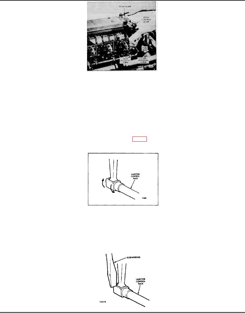
Fig. 4 - Checking Rotating Movement of Injector Control Rack
the injector control tube. Then alternately tighten both the inner and outer adjusting screws.
NOTE: Overtightening the injector rack control lever adjusting screws during installation or adjustment can result
in damage to the injector control tube. The recommended torque of the adjusting screws is 24-36 in-lb (3-4 Nm).
The above steps should result in placing the governor linkage and control tube in the respective positions that they will
attain while the engine is running at full load.
5.
To be sure of proper rack adjustment, hold the stop
Fig. 5 - Checking Injector Control Rack "Spring"
Page 101