TM 5-3895-373-34
D.
REPAIR - Continued.
CONNECTING ROD ASSEMBLIES
Type.....................................................................................................................H-section, wedge-shaped small end
Cap location to connecting rod.....................................................................................................................Serrations
Parent bore diameters
Big end.................................................................................................2.6460 to 2.6465 in. (67,21 to 67,22 mm)
Small end.........................................................................................1.65625 to 1.65725 in. (42,07 to 42,09 mm)
Length from center line of big end to center
line of small end...................................................................................8.624 to 8.626 in. (219,05 to 219,10 mm)
Big end width...................................................................................................1.577 to 1.580 in. (40,06 to 40,13 mm)
Connecting rod end float on crankpin..............................................................0.0085 to 0.0145 in. (0,21 to 0,37 mm)
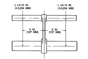
CONNECTING ROD ASSEMBLY ALIGNMENT
NOTE
Large and small end bores must be square and parallel with each other within the limits of 0.010
in. (0,25 mm), measured 5.0 in. (127 mm) each side of the axis of the rod on test mandrel with the
small end bush fitted, the limit of 0.010 in. (0,25 mm) is reduced to 0.0025 in. (0,06 mm).
CRANKSHAFT ASSEMBLY
NOTE
Crankshaft assembly is tufftrided and must be retufftrided after any regrinding. When retufftride
facilities are not available, a factory replacement crankshaft assembly should be obtained.
Overall length ..............................................................................................24.01 to 24.04 in. (609,85 to 610,62 mm)
Main journal diameter..................................................................................2.9984 to 2.9992 in. (76,16 to 76,18 mm)
GO TO NEXT PAGE
2-199


