TM 5-3895-373-20
2.10.2.
General
Diagnostic
and
STE/ICE-R
Maintenance Procedures. Throughout the diagnostic
maintenance
procedures,
access
door(s),
access
cover(s), and panel(s) must be removed or opened.
When a diagnostic step requires this, the access door(s),
access cover(s) or panel(s) are listed under the
reference information for that step. All access door(s),
access cover(s), and panel(s) open/close/removal/install
procedures are in TM 5-3895-373-10. The engine
access
cover
and
screed
cover
plate(s)
removal/installation is in paragraph 2.22.
Open or remove the listed access door(s), access
cover(s), or panel(s) and perform the task before going
on to the next access door(s), access cover(s), or
panel(s). The fault/failure may be under the first panel.
After a fault is corrected, ensure all access door(s),
access cover(s), and panel(s) are closed/installed per
TM 5-3895373-10 or paragraph 2.22.
In
certain
steps
of
the
diagnostic
maintenance
procedures, the STEIICE-R is used as a method of
determining the condition of the particular system. To
use the STE/ICE-R:
1.
Open center top right access door and center
top left access door per TM 5-3895-373-10.
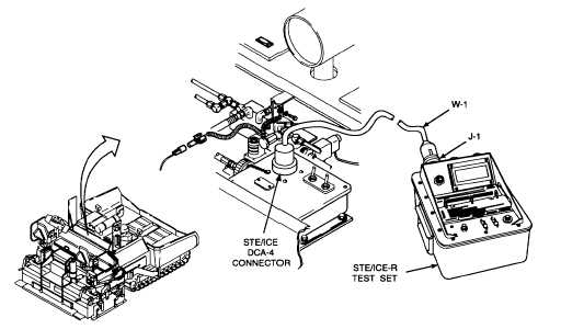
2.
Remove electrical connector cover.
CAUTION
Do
not
connect
STE/ICE-R
to
diagnostic connector DCA-4 while
STE/ICE-R
power
switch
is
on.
Damage to connector may result.
Connect DCA cable W-1 to J-1 on
STE/ICE-R before connecting to the
paving machine. Damage to the
connector may result.
3.
Use cable W-1 from the STE/ICE-R test set.
Connect cable W-1 to STE/ICE-R J-1 and to
STE/ICE DCA-4 connector.
4.
Perform STE/ICE-R confidence tests per TM 9-
4910-57112&P.
5.
Perform
STE/ICE-R
diagnostic
test
per
applicable step in diagnostic procedure.
6.
After completion of testing, set PUSH ON/PULL
OFF switch to pull off.
7.
Disconnect cable W-1 from STE/ICE DCA4
connector and from STE/ICE-R J-1.
8.
Install electrical connector cover.
9.
Close center top left access door and center top
right access door per TM 5-3895-373-10.
2-34