TM 5-3895-373-20
REFERENCE INFORMATION
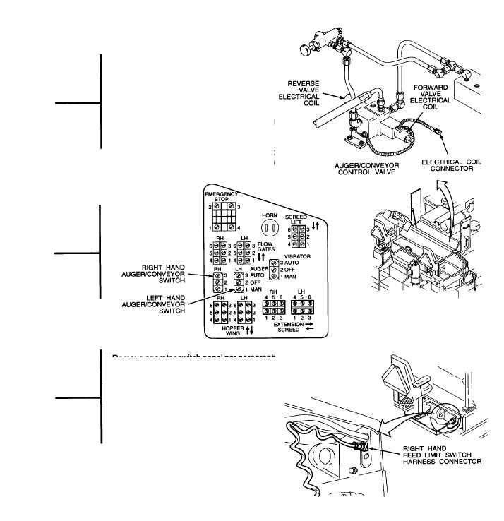
AUGER/CONVEYOR CIRCUIT
Left hand and right hand auger/conveyor
electrical control circuits are identical.
In the automatic mode, the feed limit switches turn
the auger/conveyor control valve on and off. This
controls the feeding of aggregate material to the
front of the screed. (Refer to paragraph 1.21.1 for
an
electrical
system
description
for
the
auger/conveyor circuit.)
To avoid reversing polarity to the voltmeter,
connect negative test lead to equipment ground
and use positive lead to probe for voltage.
Open center top right and center top left access
doors per TM 5-3895-373-10 to gain access to
auger/conveyor control valves.
Remove operator switch panel per paragraph 7.6 to
gain access to auger/conveyor switch terminals.
A feed limit switch is mounted on the lower, front,
inside comer of the left and right end gates. One
feed limit switch is used in each (left and right)
auger/conveyor control circuits.
Refer to paragraph 7.21 for harness and lead wire
repair.
2-315