TM 5-3895-373-20
REFERENCE INFORMATION
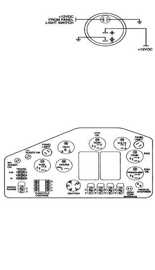
PANEL GAUGE CIRCUIT
Remove gauge panel per paragraph 7.6 to gain access
to voltmeter terminals.
To avoid reversing polarity to the voltmeter, connect
negative test lead to equipment ground and use positive
lead to probe for voltage.
Refer to the electrical system diagram at the end of the
manual for equipment wiring details.
Refer to paragraph 7.21 for harness and lead wire repair.
If the gauge is in calibration, the gauge panel voltmeter
display should be within 0.5 volts of the multimeter
reading.
A faulty voltmeter will probably indicate 0 (zero) volts.
Refer to paragraph 7.7 for voltmeter replacement
instructions.
After completing diagnostic checks, install gauge panel
per paragraph 7.6.
2-193