TM 5-3895-373-10
6. TACHOMETER
Indicates engine rotation speed (rpm) from 0 to 4000
rpm.
7.
HOURMETER
Displays the amount of time the engine has been
running in hours and tenths of hours.
8.
FUEL gauge
Indicates the amount of fuel in the fuel tank.
9.
AUGERICONVEYOR INDICATOR lights
When on, indicate the auger/conveyor system is in
automatic operation.
10. TRAVEL switch
In the down, neutral "N" position, the paving machine
will not move. In the up, forward/reverse "F/R"
position, the control handles will operate to control
the movement of the paving machine. In the down,
"N" position, the motion of the paving machine is
stopped without losing the established control handle
position. This allows the operator to resume an
established paving speed when the travel switch is
returned to the up, forward/reverse "F/R" position.
When the travel switch is in the down, neutral "N"
position, the brakes are engaged.
11. SPEED RANGE switch
This switch controls the paving machine range of
speed. In the up, "hare", travel position, the paving
machine can travel at its greatest range of speed.
This position is for traveling only and should not be
used for paving. In the down, "tortoise", paving
position, the paving machine speed is limited to the
slower paving speeds.
12. THROTTLE CONTROL switch
This switch controls the speed of the engine. In the
extreme left position, "MAX" position, the engine will
operate at its maximum rpm. In the extreme right
position, "IDLE" position, the engine will operate at
its idle rpm. Momentarily moving the switch from idle
to maximum and returning to the center, detent
position, will increase engine rpm gradually. For
additional rpm, jog the switch between the "MAX"
and center, detent positions until the desired rpm is
reached. Reverse the operation described above to
decrease rpm.
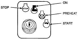
13. IGNITION switch
Controls the starting and stopping of the engine and
turns power on and off to the paving machine. In the
"STOP" position, all power to the paving machine is
turned off except power to the horn and work lights.
In the ON position, electrical power is applied to all
machine components. In the PREHEAT position, power
is provided to the engine induction heater. In the START
position, power is provided to the engine starter motor.
14. REAR WORK LIGHT switch
Turns the rear work lights ON and OFF. Work lights
will operate with the ignition switch in the stop
position.
15. AUGER WORK LIGHT switch
Turns the work lights in the auger chamber ON and
OFF. Auger work lights will operate with ignition
switch in the stop position.
16. FORWARD WORK LIGHT switch
Turns the work lights in the hopper area ON and
OFF. Forward work lights will operate with ignition
switch in the stop position.
17. PANEL LIGHT switch
Turns the control panel lights ON and OFF.
18. HIGH TEMPERATURE WARNING indicator light
The red light turns on at 214°F (101°C) engine
coolant temperature. This light warns the paving
machine operator of a high coolant temperature
before automatic engine shutdown occurs at 220°F
(104°C).
19. HIGH TEMPERATURE MANUAL OVERRIDE button
When pushed and held in, this button allows the
paving machine operator to override the automatic
engine high temperature shutdown. When pressure
on the button is relieved, the button spring returns to
the up position, disengaging the override. The
button must be held in for as long as the shutdown is
to be overridden.
20. ENGINE OIL PRESSURE gauge
Dual scale gauge which indicates engine oil pressure
from 0 to 150 psi. and 0 to 10 kp/cm2.
2-3


