TM 5-3895-371-24 & P
(8).
(29)
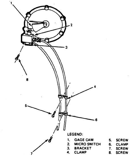
Remove micro switch (2, fig. 3-110) with attached bracket (3) by removing two screws
(30)
Remove screws (5 and 7) and attached clamps (4 and 6). Lay the cable aside,
(31)
Remove burner assembly (1, fig. 3-111) by removing two capscrews (4) and washers that
fasten the assembly to the tank; and screw (3) that joins the two tubes together. Disconnect oil feed
line (2) and pull off the burner assembly (1) with the tapered spacers located behind the burners.
Figure 3-110. Disconnect/Connect Micro Switch and Cables.
TA 075984
3-93

