
Engine Tune-Up
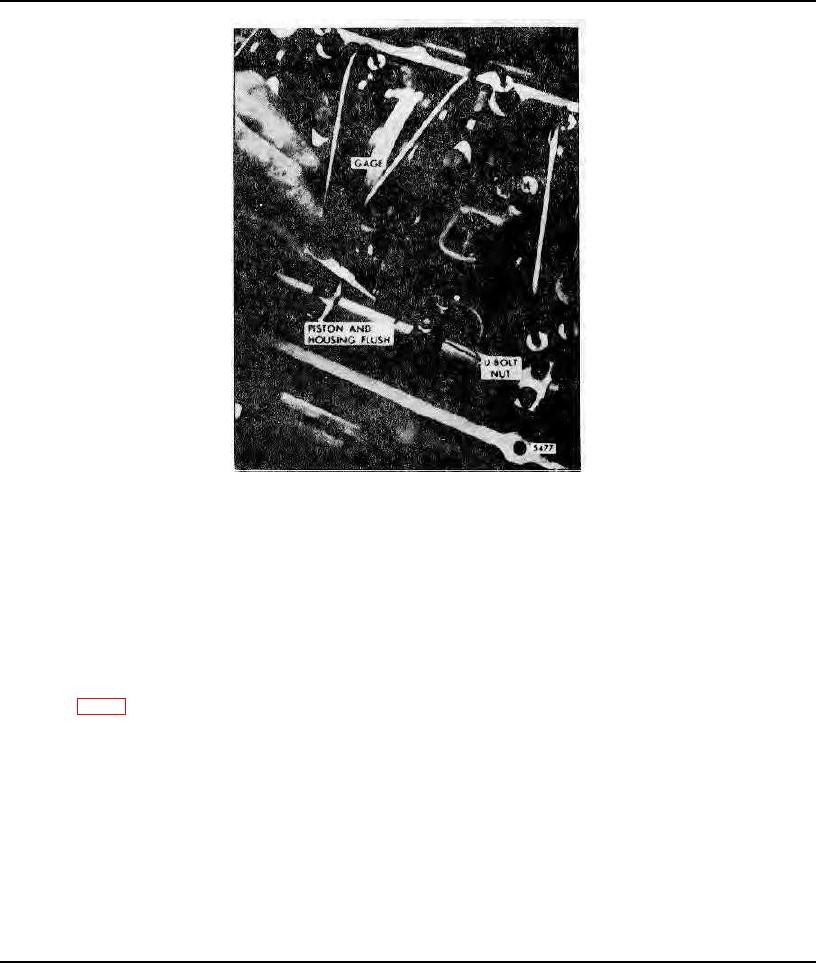
Fig. 5 - Adjusting Throttle Delay Cylinder
To inspect the check valve, fill the throttle delay cylinder with diesel fuel oil and watch for check valve leakage while
moving the engine throttle from the idle position to the full fuel position.
Adjustment
Whenever the injector rack control levers are adjusted, disconnect the throttle delay mechanism by loosening the U-bolt
which clamps the lever to the injector control tube. After the injector rack control levers have been positioned, the
throttle delay mechanism must be re-adjusted. With the engine stopped, proceed as follows:
1. Refer to Fig. 5 and insert gage J 23190 (.454" setting) between the injector body and the shoulder on the injector
rack. Then exert a light pressure on the injector control tube in the direction of full fuel.
2. Align the throttle delay piston so it is flush with the edge of the throttle delay cylinder.
3. Tighten the U-bolt on the injector control tube and remove the gage.
4. Move the injector rack from the no-fuel to full-fuel to make sure it does not bind.
Page 107