TM 5-3895-373-20
A.
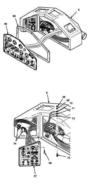
REMOVE - Continued.
h.
Remove gauge panel assembly (46) from
operator control console (8).
i.
Remove panel seal (65). Discard panel seal.
7.
REMOVE SWITCH PANEL ASSEMBLY AND
PANEL SEAL FROM OPERATOR CONTROL
CONSOLE.
a.
Remove button head cap screws (66).
CAUTION
Do not allow switch panel assembly
to
hang
from
wires
and
wiring
harnesses. Excessive strain on wires
and wiring harnesses may result in
damaged
or
broken
wires
and
connections.
b.
Remove switch panel assembly (67) far
enough from operator control console (8)
to allow room to work on back side of
switch panel.
c.
Remove self-locking hex nut (68), flat
washer (69), ground wires (70, 71, and
72), and button head cap screw (73). Tag
ground wires. Discard self-locking hex
nuts.
d.
Tag and disconnect electrical connector
(74).
e.
Cut and remove tie wraps as needed.
Discard tie wraps.
GO TO NEXT PAGE
7-31