TM 5-3895-373-20
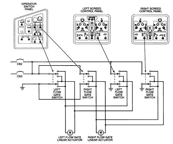
1.18.7. Flow Gate Electrical Circuit. The flow gate
electrical circuit consists of four toggle switches and two
reversible, linear actuators. All four switches are double-
pole/double-throw (DPDT), three-position (center off),
and spring-loaded return to off.
The operator switch panel controls both flow gates with a
left flow gate switch and a right flow gate switch. Each
screed control panel also controls the flow gate on that
side.
Circuit breakers CB2 and CB3 jointly power the flow gate
circuit. Each flow gate switch has two inputs. One input
is 12 VDC. The other input is ground. Placing the flow
gate switch in the up, RAISE position, applies 12 VDC to
one output line and ground to the other. The flow gate
switch output drives the flow gate linear actuator. The
flow gate linear actuator contains a reversible DC motor.
Placing the flow gate switch in the down, LOWER
position, reverses polarity to the output contacts, and the
linear actuator reverses direction.
1-32