TM 5-3895-373-20
REFERENCE INFORMATION
HYDRAULIC CYLINDER CIRCUITS
TEST
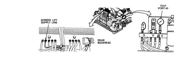
PORT #5
SCREED LIFT CYLINDERS - PRESSURE CHECK PROCEDURE
1.
With engine running at MAX speed, lift screed to
fully-raised position. Place cribbing below both
ends of main screed, leaving 1 to 1-1/2 in. air
gap between screed plate and cribbing.
2.
Support screed in fully-raised position with
hydraulic jacks at rear flanges of screed tow
arms.
3.
Turn paving machine off. Use hydraulic jacks to
adjust screed height so that screed lift cylinder
clevis pins turn freely in cylinder mounting
knuckles.
Make sure lift cylinders are not under
load before removing hydraulic hoses
from lift cylinder retract ports. Hydraulic
oil under pressure can penetrate skin or
damage eyes.
4.
Make sure lift cylinders are not under extension
or compression load. Disconnect hoses from
bottom (retract) port elbows of screed lift
cylinders. Plug hose ends and cap off cylinder
retract port elbows; use #6 JIC (9/6-18) high
pressure caps.
NOTE
When hydraulic jack is lowered, screed is expected to
drop slightly. This initial drop will make up for fluid loss
that occurred during removal of supply hoses from
cylinders.
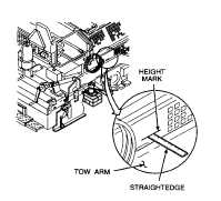
5.
Release both hydraulic jacks at the same time.
When screed is stable, use straightedge and
pencil to mark vertical position of left and right
tow arms.
6.
After 1/2 hour, mark settled position of screed
tow arms. Measure distance between upper and
lower pencil marks on left and right side of
screed. Answer question in paragraph B5 of
flowchart.
7.
Support screed in raised position with hydraulic
jacks at rear flanges of screed tow arms. Adjust
screed height to remove load from screed lift
cylinders.
8.
Remove plugs and caps and reconnect screed
lift cylinder hoses.
After completing diagnostic checks, close right, center
top left, and center top right access doors per TM 5-
3895-373-10.
2-275