
TM 5-3895-385-23-2
0224
Screed Installation -- Continued.
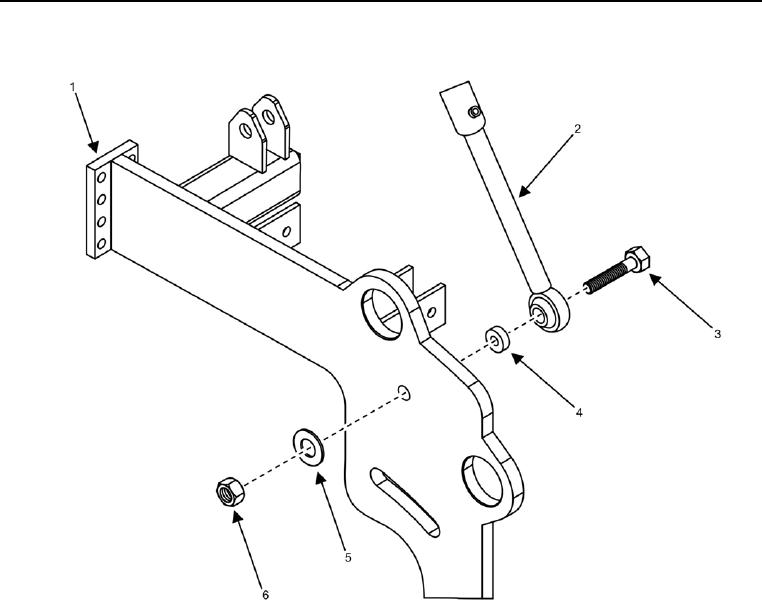
Figure 6. Screed Raise Hydraulic Cylinder -- Connect.
NOTE
It may be necessary to place screed into float setting in order to move screed raise hydraulic
cylinder up or down to align mounting holes.
7. Install bolt (Figure 6, Item 3), screed raise hydraulic cylinder (Figure 6, Item 2), spacer (Figure 6, Item 4), flat
washer (Figure 6, Item 5), and new lock nut (Figure 6, Item 6) into screed arm (Figure 6, Item 1).

