TM 5-3895-373-20
REFERENCE INFORMATION
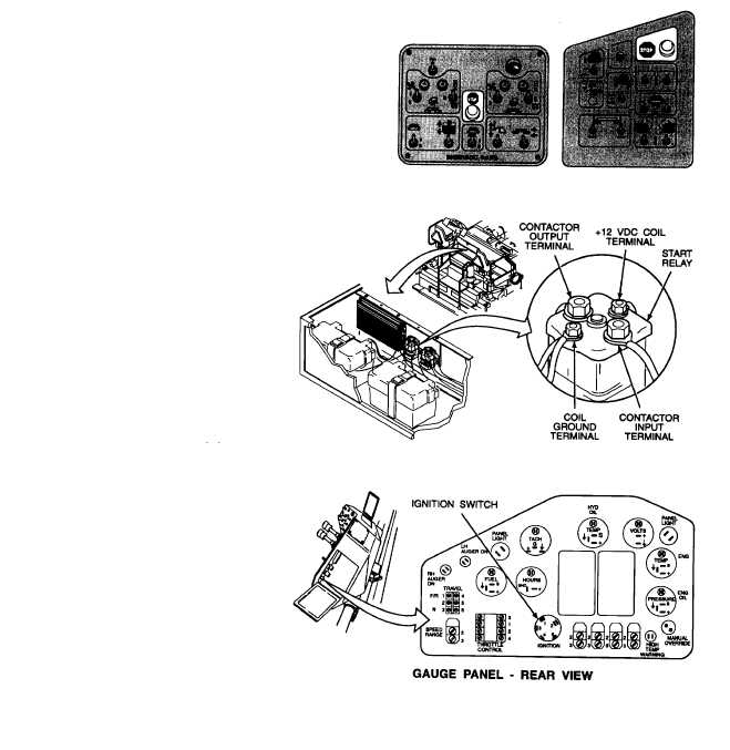
IGNITION/EMERGENCY STOP CIRCUIT
Refer to TM 5-3895-373-10 for engine starting and equipment operating procedures. Refer to paragraph 2.10 for
connecting and disconnecting STE/ICE-R test set to DCA. Refer to paragraph 1.18.1 for a description of the emergency
stop circuit.
An emergency stop switch is located on the switch panel
and at each of the screed control panels.
The three emergency stop switches are connected in
series. If any one of the three switches is pressed,
paving machine electrical power is shut off.
During engine cranking, voltage across relay coil
terminals is reduced by starter current draw.
Open rear top left access door per TM 5-3895373-10 to
gain access to start relay.
Remove switch panel per paragraph 7.6 to gain access
to ignition switch terminals.
After completing diagnostic checks, close rear top left
access door per TM 5-3895-373-10 and install engine
access cover per paragraph 2.22.
2-137