TM 5-3895-373-20
15.3.
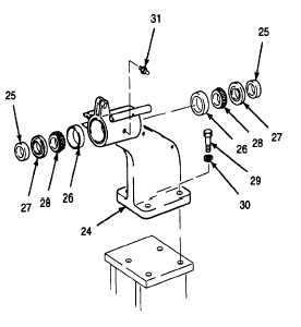
REPLACE THICKNESS CONTROL COMPONENTS - Continued.
A.
REMOVE - Continued.
2.
REMOVE
MOUNTING
BRACKET
COMPONENTS.
a.
Insert drive pin punch through center of spacer
(25). Working around outer perimeter of
opposite bearing cup (26), slowly drive spacer,
seal (27), tapered cones and rollers (28), and
bearing
cup
from
mounting
bracket
(24).
Discard plain encased seal and tapered cones
and rollers.
b.
Repeat bearing removal procedure, step a, from
opposite end of mounting bracket.
NOTE
Removal
of
the
following
components is only required when
replacing damaged mounting bracket
or attaching parts.
c.
Remove hex head cap screws (29), lockwashers
(30), and mounting bracket (24). Remove
lubrication fitting (31) from mounting bracket.
Discard lockwasher.
GO TO NEXT PAGE
15-22