
TM 5-3895-356-14&P
Figure 128.
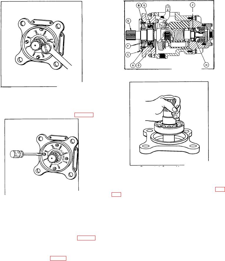
Pre Phase III pump cross section drawing
Figure 126.
Removing shaft seal retainer bolts
If shaft seal retainer (57) does not contain the two 1/4"
threaded holes, tap the sides of the bolt hole
counterbores lightly to break the gasket seal. Using a
screw driver, remove seal assembly (57) See Fig. 127.
Figure 129.
Removing shaft assembly
EXCEPTION
On units with an 8 inch square flange (pre Phase III) the
shaft is removed from the back of the flange. See Fig.
Figure 127.
A. Reverse mounting flange (C) and remove
Removing shaft seal retainer
retainer ring (D) using truarc pliers.
19. Remove shaft seal (56) from retainer (57) using an
arbor press and a 21/2" plug.
B. Remove pump shaft (E) and assembled
parts (F, G, H, and J) by pulling shaft (E) straight
20. Remove square ring (29) from flange.
up from back of mounting flange (C).
EXCEPTION
22. Inspect ball bearing (30) for galling, roughness or
In the absence of the O ring and groove, remove retainer
cage cracks. If damage is evident, remove retaining
gasket (A) from retainer (B) or flange (C). See Fig. 128.
rings (55) (or F is applicable) using truarc pliers and
press ball bearing (30) from shaft.
21. Remove pump shaft and assembled parts (1, 30, 55,
49 and inner race of 50) by pulling straight up from
23. Inspect the inner race of roller bearing (50) (or J if
mounting flange (2), as shown in Fig.129.
applicable) for galling or roughness. If no damage is
apparent and if no damage was observed when the
outer race was inspected in Step 7, then it is not
necessary to remove the inner race from the shaft.
If, on the other hand, damage to either the inner or outer
.race is observed, BOTH must be
95

